Many radiosity systems are sensitive to the quality of geometric data passed to them as input. This is an understandable limitation, but it places extra burden on users of the system if they have to ensure that the quality of their geometry is high enough for it be used in a radiosity calculation. Ideally, users would like to pass their input geometry into the calculation and hope that any errors in this geometry will be either corrected or otherwise handled. The problem of dealing with imperfect geometry is exacerbated by the need to handle data in many formats. The burden of dealing with problematic geometry should not, however, fall upon the radiosity system itself. In order to maximise the performance of the radiosity system it is important that it is able to make simplifying assumptions about its input data. Any approach which aims to improve the handling of input geometry must therefore leave the radiosity system to concentrate on its primary job: performing the radiosity calculation.
As part of the ARCADE project we have begun to address the problems outlined above. The main thrust of this work has been to extend the set of tools within LADS that can be used to provide high-quality geometry, even if initially the geometry available is less than perfect.
The new functionality to be developed includes enhanced initial triangulation tools, tools for ensuring normal consistency, and mesh simplification or unmeshing. Note that all the tools described here can be used outside of (as well as in combination with) the radiosity module.
What is "normal consistency" ? Well, normal inconsistency, is when the normals of some of the polygons in a polymesh, have been erroneously reversed. A normal consistency algorithm, is one which tours the polymesh and "flips" the erroneous polygons. Normal inconsistency often arises when a polymesh has been through one or more file format conversions, and some polygon normals have got confused along the way. Most often visible to the viewer as a "vase with holes in it", it can also arise when the API user has simply defined polygons in the mesh incorrectly (i.e., defined the vertices with the wrong sense). LightWorks now provides tools which can be used to ensure that the normals for a given mesh are consistent.
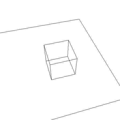
A question to consider is then, given two polygons in a mesh, when are the two regarded as being mutually consistent, and when are they mutually inconsistent? If these polygons share no edges and no vertices, then we are unable to make any decision regarding the consistency of their normals. The same is true if they share only vertices. However, if they share an edge, then we can examine the direction this edge was traversed in, when each of the polygons was defined. If they traversed the edge in opposite directions, then they are consistent. Otherwise, they are inconsistent. Figure 1 illustrates this point.
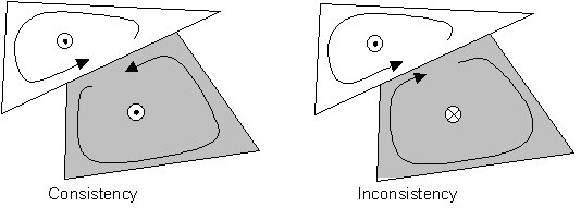
Figure 1: Normal Consistency depends on Polygon Winding
It is therefore possible to identify inconsistent cases and re-wind either of the polygons to make them a consistent pair. The question arises: which polygon is wrong? It is easy to see how this approach could end up producing exactly the wrong the result, with all polygons in the mesh pointing the wrong way, rather than just some!
If the correct orientation of just one polygon in the mesh is known, then this can be treated as a seed polygon, and used to correct all of the polygons with which it shares an edge. These, in turn can correct all of their neighbours and so on. The process can propagate through the mesh until all the polygons which are joined in this way are correctly oriented. It is worth restating at this point however that an attempt to make an entire mesh consistent in this way can fail for polygons which only join at their vertices, or do not join at all as figure 2 shows.
Figure 2: Not all polygons can be reached via edge/edge boundaries
Once a mesh has been made consistent, it represents either the correct result, or a mesh which simply needs every polygon reversing, in order to get the correct result. The API functions which can be used to get to this point are as follows:
LtPref LiPrimitiveConsistentParts ( LtPrim prim )
LtPref LiPrimitiveReferenceConsistentParts ( LtPref pref )

LtStatus LiPrimitiveReverse ( LtPrim prim )
LtStatus LiPrimitiveReferenceReverse ( LtPref pref )
The first of these routines, LiPrimitiveConsistentParts, accepts only polymesh primitives as input. The routine picks a single polygon from the mesh, and ensures that all other polygons in the mesh have a winding which is consistent with the chosen polygon. If some polygons cannot be joined to the chosen polygon by edge/edge boundaries (see Figure 2) then these polygons will be removed from the input primitive and bundled into a new mesh. This new mesh will itself be passed to LiPrimitiveConsistentParts and the result appended to the (now consistent) input primitive using a primitive reference. The resulting list of consistent primitives comprises the function's return value.
LiPrimitiveReferenceConsistentParts will call LiPrimitiveConsistentParts for each primitive in the input primitive reference list. The results from the low-level calls will be merged to provide the top-level return value.
The following meshing criterion is important to these two functions:
LI_MESH_CRIT_VERTEX_NORMALS
This expects an enumerated value, and will accept any of the values: LI_NORMALS_UNKNOWN, LI_NORMALS_TRUSTWORTHY and LI_NORMALS_UNTRUSTWORTHY. This tells the processing routines whether they should be guided by the orientations of any vertex normals which are present. If these values are trustworthy, then polygon normals will be oriented so that they point into the same half-space as the mean of all the polygon's vertex normals. Otherwise, vertex normals will be ignored. Note that normally a mesh which comes in five disjoint parts, for example, will result in five distinct meshes when split into consistent parts. However, if trustworthy vertex normals are present, then only a single primitive may result.
All primitives generated by these routines will be flagged LI_PRIM_FLAG_CONSISTENT. If a user is certain that they have a consistent mesh, without any help from the API, then they can tag their primitives as being consistent, with LI_PRIM_FLAG_CONSISTENT. No consistency processing will be carried out on such primitives.
Once the input primitives have been split up into consistent meshes, the user can selectively reverse the orientation of an entire mesh, using LiPrimitiveReverse. Similarly a list of primitives can have their orientations reversed using LiPrimitiveReferenceReverse.
Two further API functions are provided. The first of these provides a higher-level interface to the functions already introduced:
LtStatus
LiPrimitiveConsistentPolygon (
   LtPrim      prim,
   LtPoly      poly,
   LtBoolean   nice_poly
)
This takes a polymesh, a polygon from that mesh, and an indication of whether the polygon is correctly oriented (TRUE) or not (FALSE). If the polymesh is already consistent, and the polygon is already correctly-oriented, then there is no further work to do. If the polygon is wrongly-oriented, then the function will call LiPrimitiveReverse , to fix things. If LI_PRIM_FLAG_CONSISTENT is not set, then LiPrimitiveConsistentParts will be called. If more than one primitive results, the routine will fail, because one polygon is not sufficient to resolve the situation (it can only lie in one mesh). If a single polymesh results, we proceed as we did for the consistent mesh that was passed in (taking care to notice whether the input polygon has flipped orientation, or not).
The final API addition is:
LtPref
LiPrimitiveReferenceConsistentSolid (
   LtPref      solid,
   LtBoolean   outside_of_interest
)
This takes as input a list of meshes which, together, make up the boundary surface of a closed, solid object. If any of the meshes are not consistent, then they will be made so before processing continues. As an example of this routine's application consider six meshes which constitute the faces of a cube. These meshes can be passed to LiPrimitiveReferenceConsistentSolid, together with TRUE, with the result being that the meshes are oriented to face away from the cube centroid. However, if the same meshes represented the walls of a cubic room, then the value of the second parameter would be set to FALSE, and the meshes would all be made to face the centroid of the room.
LiPrimitiveReferenceConsistentSolid will produce erratic results if passed geometry which does not constitute the boundary of a closed solid.
The tools described so far are concerned with correcting problems which are typically found in relatively complex meshes. A related, but somewhat different approach is to simplify the geometry of interest as far as this is possible before dealing with it any further.
The following API will perform the unmeshing of any primitive which is passed to it.
LtPrim
LiPrimitiveSimplifyMesh(
   LtPrim    the_mesh,
   LtBoolean keep_original
)
The input consists of the primitive to be simplified and a flag which determines whether the input primitive should be left alone and the simplification performed on a copy (TRUE) or whether the input mesh itself can be simplified (FALSE). The returned primitive is a simplified version of the input or NULL if an error occurred. Note that input primitives must be of type LI_PRIM_TYPE_MESH. Any other primitive types will result in an error and the return of a NULL primitive. Input meshes must also be consistent (see discussion above). If they are not then again an error will occur and a NULL primitive will be returned.
An additional API function is also provided for simplifying a list of mesh primitives in one go. Here the return value is a linked list of simplified primitives which result from sequential calls to LiPrimitiveSimplifyMesh for all primitives on the input list. The API function to use for a list of primitives is:
LtPref
LiPrimitiveReferenceSimplifyMesh(
   LtPref    mesh_list,
   LtBoolean keep_originals
)
Note that only successful calls to LiPrimitiveSimplifyMesh made by LiPrimitiveReferenceSimplifyMesh will result in any addition to the output list. If no successful calls to LiPrimitiveSimplifyMesh were made then the output list will be NULL.
Reference pages are also available for LiPrimitiveSimplifyMesh and LiPrimitiveReferenceSimplifyMesh.
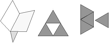
An example of the unmeshing code in action is shown below. Here the image on the left is a meshed up version of a simple scene as generated by the radiosity module. The central image shows the underlying mesh. If, for whatever reason, it was necessary to simplify the geometry as far as it is possible to do this, a single call to LiPrimitiveReferenceSimplifyMesh can produce the much simpler geometry shown in the right-hand image.
![]()
Restricted information.
© LightWork Design Ltd. All information contained in
this document is the copyright of LightWork Design Ltd. (unless stated
otherwise) and may not be used or reproduced with prior written consent.
![]()