Practical 2: Texture mapping
The deadline for giving back TP2 is: Wednesday, November 16th (midnight, European Time)
Classical texture mapping
The C++ code contains everything to load a texture from a file, store it a Qt structure and pass it as a parameter to the shaders:
      glActiveTexture(GL_TEXTURE0);
      texture = new QOpenGLTexture(QImage(textureName));
      texture->bind(0);
      m_program->setUniformValue("colorTexture", 0);
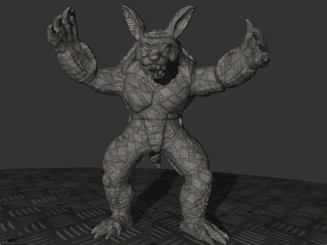
Your first task is to write a shader, 3_textured, to map this texture onto the model and the ground. You will have to use the texture coordinates, texcoords, and query the texture value at this point. The shader used for the ground is always 3_textured; you will be able to see the effect of your shader on the ground.
You can only texture a model if it defines texture coordinates. All models whose name ends with "Tex" define them. For the others, texcoords is always null. Your shader wil display the texture pixel of coordinates (0,0).
You can combine these textures with the shading program you wrote for the previous practical, with the color defined by the texture.
 |
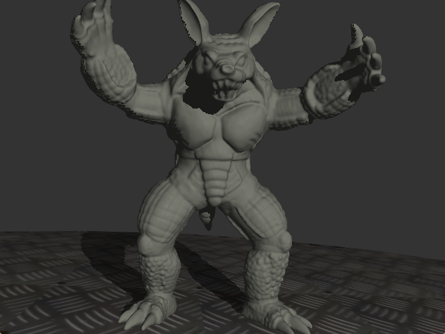 |
| "armadilloTex" model | "armadillo" model |
Computing texture coordinates
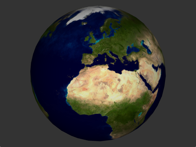
Your next task is to compute texture coordinates yourself. We will work on the sphere model (any of them). The 4_earth shader loads the earthDay texture, defining the color of all points on Earth.
Your have to compute texture coordinates in the fragment shader, and use them to map this texture onto the sphere.
You will have to pass world coordinates to the fragment shader, in order to have the position on the sphere.
You can also combine this texture with the shading algorithm you wrote in the previous practical
Normal mapping
We will now add some relief to the globe, using bump mapping. Your shader has access to a texture, earthNormals, containing perturbed normals in a local frame (normal, tangent, bi-tangent).
The view vector and the light vector are expressed in world coordinates. The perturbed normal, is in this local frame. To do lighting computations, you will have to convert all vectors to the same frame.
To do this, compute the transformation matrix for the local frame of the perturbed normal . The z axis is the geometric normal, . You will have to compute the tangent vector and bi-tangent , consistently with your texture parameterization. You then get a transformation matrix for the local frame:
You have to combine it with the object transformation matrix to have the transformation from local frame to global frame, the one used for shading computations.
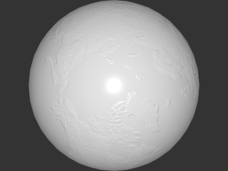
For debugging, start by displaying only the shading computations, without the underlying color. Check that the continents do appear as elevated, both for North-South coastlines and for East-West coastlines (depending on your and vector orientations, these can behave differently).
 |
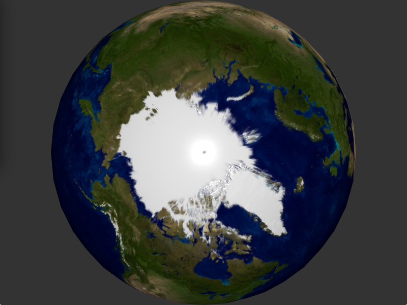 |
| Shading with perturbed normals only | Combined result |
Please note that the texture earthNormals contains the vector coordinates in . You will have to convert them to before you do your shading computations.
Environment mapping
We now load an environment map. It contains distant lighting, stored in spherical coordinates :
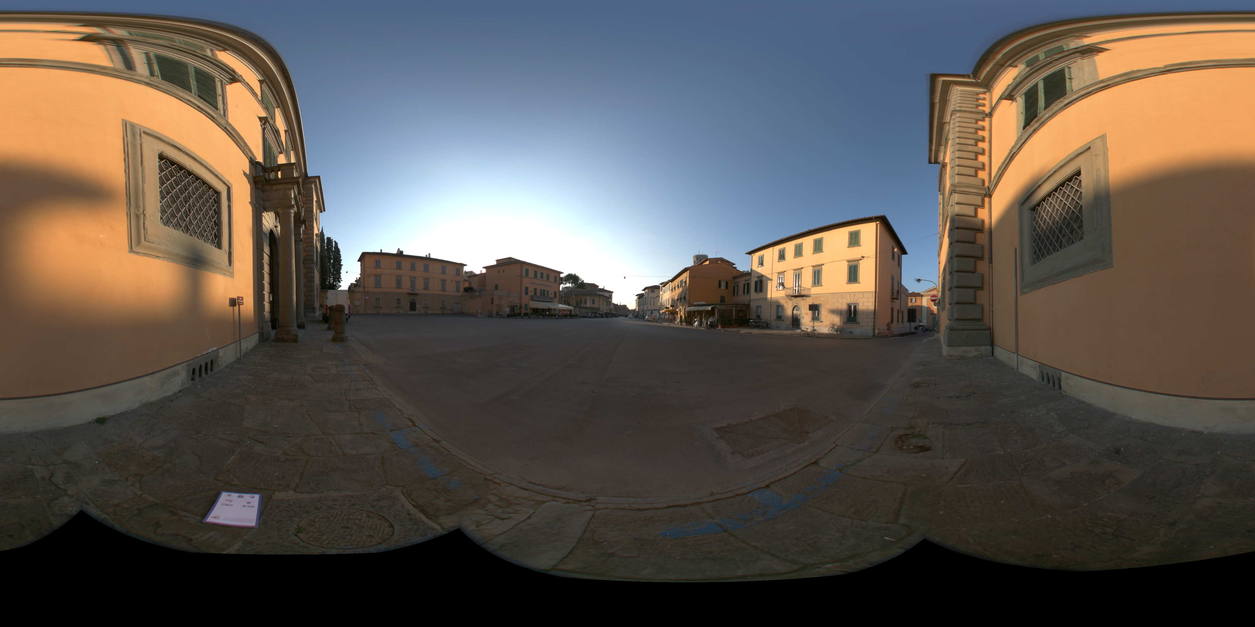
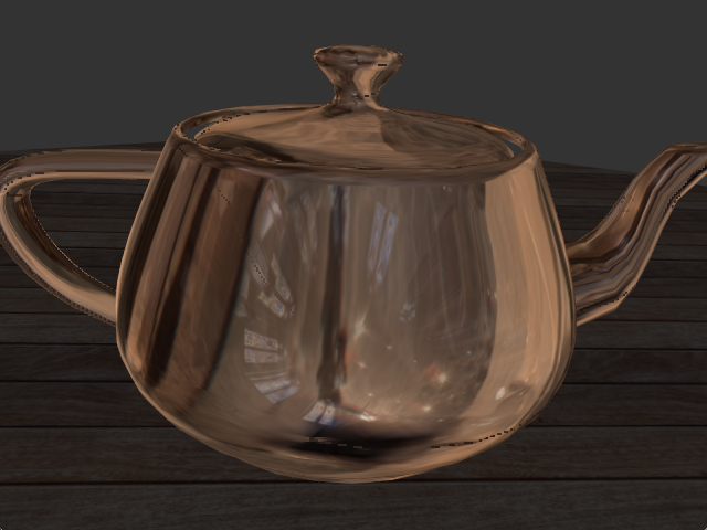
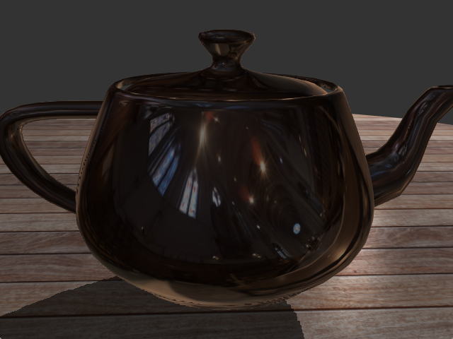
In the shader 5_envMap, you will have to use this environment map to render specular objects. We start with a metallic (opaque) object, with only reflection. For each image pixel, you have the eye ray and the normal. Use them to compute the reflected ray and query the environment map in this direction.
Once this works, extend it to transparent objects. For each pixel, you now have two rays: the reflected ray (the one you just did) and the refracted ray, whose direction depends on the index of refraction . The amount of energy reflected and refracted depends on the Fresnel coefficient, which we computed in the previous practical:
with:
The color of the reflected ray must be multiplied by the Fresnel coefficient, that of the refracted ray by .
